Porygon is a circuit built with commodity hardware designed to automate actions on a Nintendo Switch Joycon.
For discussion or questions, use the issues page on the companion GitHub repo.
Background
As you can see on the about me page, I was absolutely the right age to explore the magical land of Kanto when Pokémon Red/Blue came out in ‘98. I won’t remember to get a loaf of bread at the store, but I still remember burning my masterball on Zapdos and regretting it later. As video games go, those were some intensely fond memories.
So many people feel the same way as I that Nintendo did a remake called Pokémon Let’s Go. It is a
remake of the classic – adding some new twists to keep things fresh, but keeping most of what
32-year-old nostalgia junkies I loved about it in the first place.
After buying and playing through the game, I came across a peculiar feature. Certain events in the game have random output – for example, when you trade a Helix Fossil in for an Aerodactyl, the Aerodactyl will have randomized stats. If you don’t like the stats, you can reset without saving to sort of go “back in time”, to right before you handed over the fossil. And then you roll those sweet dice again.
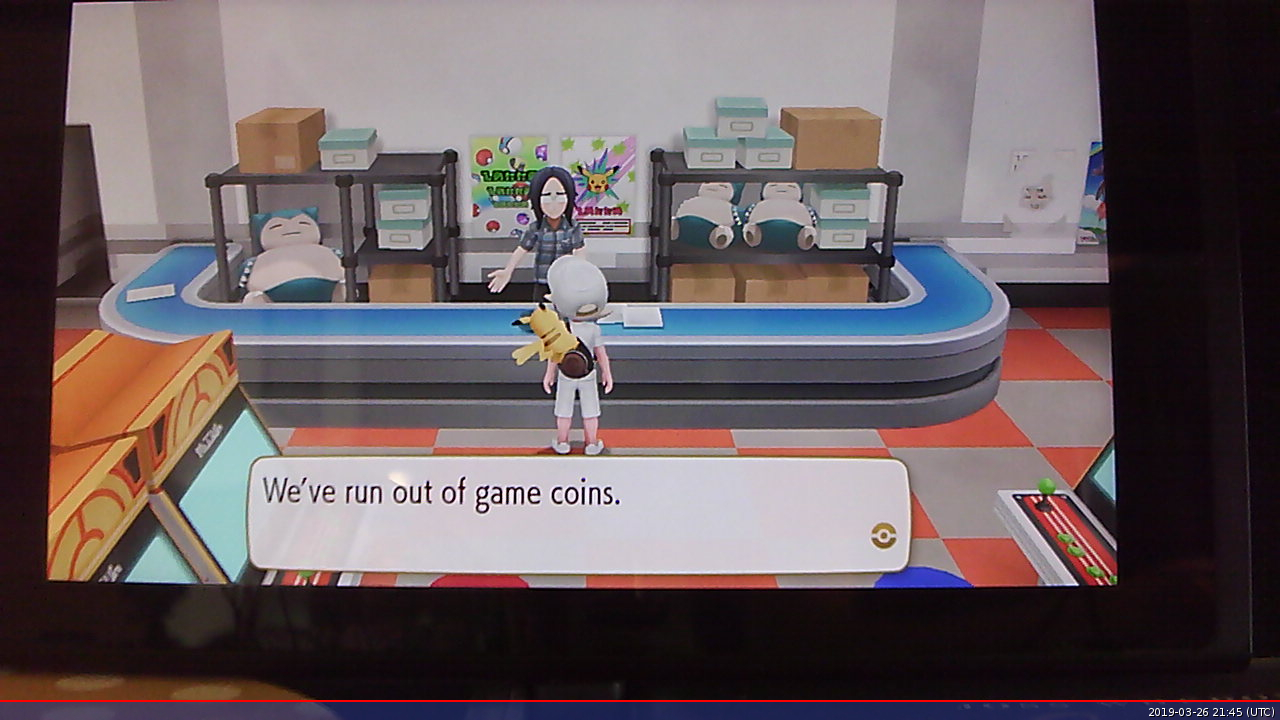
Another such place is for farming “Gold Bottle Caps.” These are rare items that you trade to an NPC, and in exchange he improves whichever Pokémon you give to him. The only place these spawn (outside of scripted in-game events) is in a building called Rocket Corner. You can pick up the items and, if you want, use the soft-reset trick to try again. Eventually, you’ll get the rare one you want.
I thought that, if any task in this game were automatable, it would be that one. So while this methodology will generalize to other JoyCon based inputs, the task at hand here is to farm Gold Bottlecaps automatically.
Acknowledgements
- A modder named dekuNukem has the defacto home page for reverse engineering the Nintendo Switch. He, and the folks who contribute to that repository, have figured out a whole lot.
- The ##electronics channel in Freenode usually had someone willing to help me out, from soldering technique to digital circuit basics.
- Mahmoud Hashemi for general advice on sharing software.
Implementation
“The device” is conceptually easy to understand:
- Parts of a JoyCon controller are connected to a custom digital circuit.
- The custom digital circuit takes inputs and power from the GPIO pins of a raspi.
- The raspi runs Linux, and is hooked up to a webcam pointed at the screen.
- The raspi uses OCR to read the screen and detect what actions are required from the joycon.
The joycon
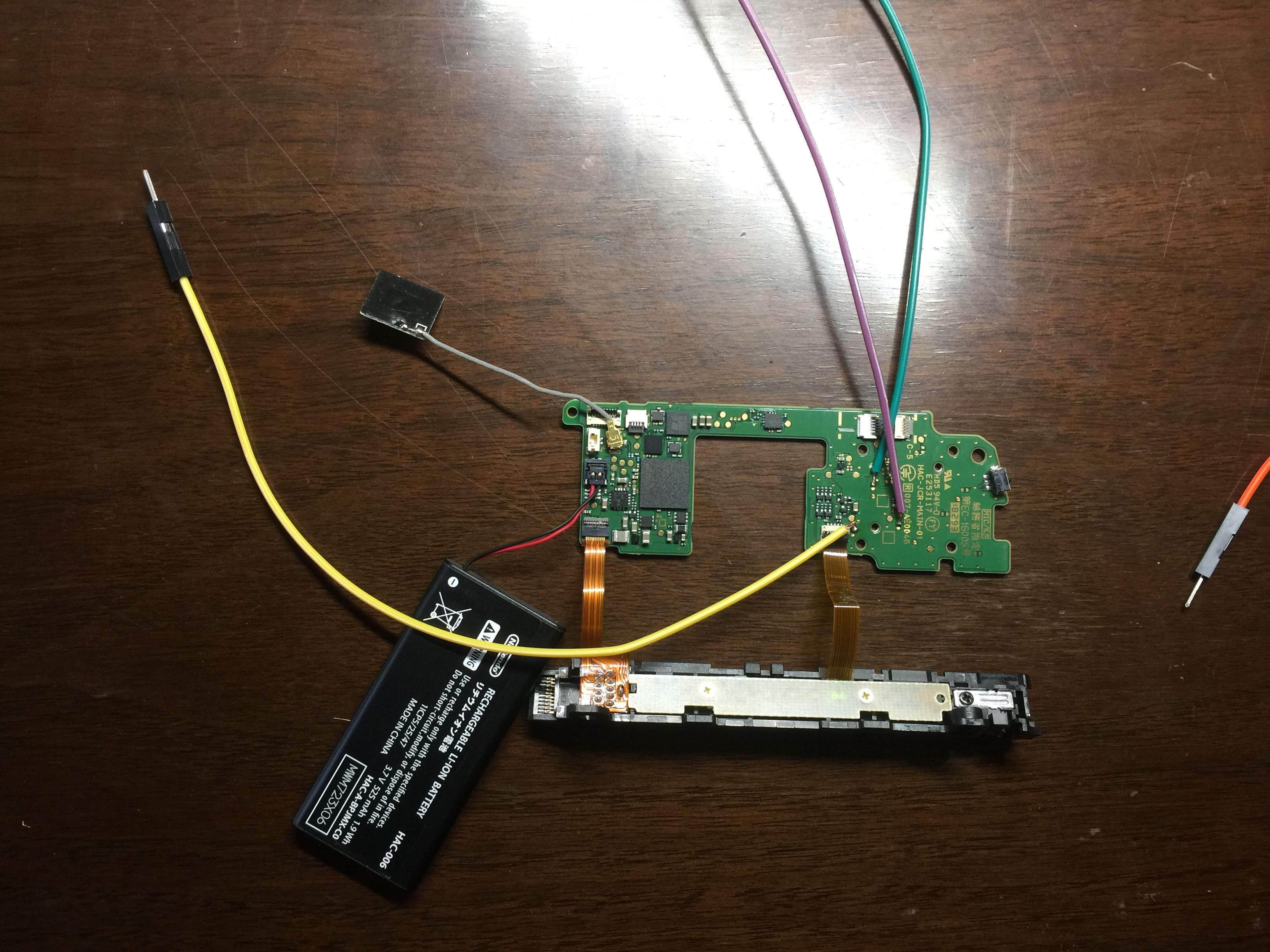
This project starts with a pretty steep barrier to entry. The above picture shows the PCB for a right JoyCon, as manufactured in 2018. You can fit a penny inside the rectangular hole in the center – and what you’re soldering to is way smaller than that.
First, pair the joycon with your switch. It’s harder to do once you’ve taken things apart :).
Then, you’ll need to access the main PCB. The inside of a JoyCon actually has a lot of other stuff in it. There are some tear-down videos on the web, but it’s pretty easy to figure out. You’ll see that I left two ribbon cables, connecting the PCB to the sliding assembly. We’ll need those for access to the Reset button and also to power the main board. You’ll also need an uncommon tri-wing screwdriver. There are repair kits on Amazon which have one.
At this point you may want to play around with the test points. Taking a jumper wire, you can join COL with A/B/X/Y to simulate a button press. This will actually do stuff to the console it’s paired with! Assuming your battery has any charge.
Using the pinout on dekuNukem’s repository, you need to solder jumper cables to all the test pads POTX, POTY, A, B, X, Y, COL, and HOME. Home is missing on the pinout – it’s the circular pad to the west of the bottom philips head screw of the joystick.
Soldering to such small equipment is difficult. And if you apply too much heat, the copper pads will pop off the PCB, and you won’t be able to use it in your circuit! I went through a lot of joycons that way. So here is some soldering advice:
- Use jumper cables that are meant for a breadboard. Leaving one male side intact, strip the wire off the other side to reveal the underlying copper cables. They should have pretty thin strands. You want enough strands for solder to grab on to, but not so many that the strands get in the way of heating the test point.
- Use a soldering tip appropriate for the job. It should be small enough to only touch the pad you are working on, but not so small that heating the whole pad becomes difficult.
- Use 600F for your soldering iron (or a 20W unregulated iron). You want to get in and out quickly – too much heat and you will lose the copper pad forever.
- Using flux core, tin/lead alloy solder, tin the pad. You heat the pad and feed solder on to it, resulting in a blob.
- Add flux to the blob.
- Use one hand to place the wire on the fluxed blob. Use another hand to move the iron to reheat the blob. (Unless you’re a surgeon, your shaky hands will be really frustrating here).
- The solder will wick in to the copper strands. Remove the heat, blow on the joint, and release the wire.
These joints are seriously delicate. Don’t apply any more stress to them than necessary for moving them around and plugging them in to the breadboard.
On the bottom of the slider assembly, there are 10 pins. Connecting pin 4 to 5V and grounding it out through pin 1 will power the whole PCB.
The circuit
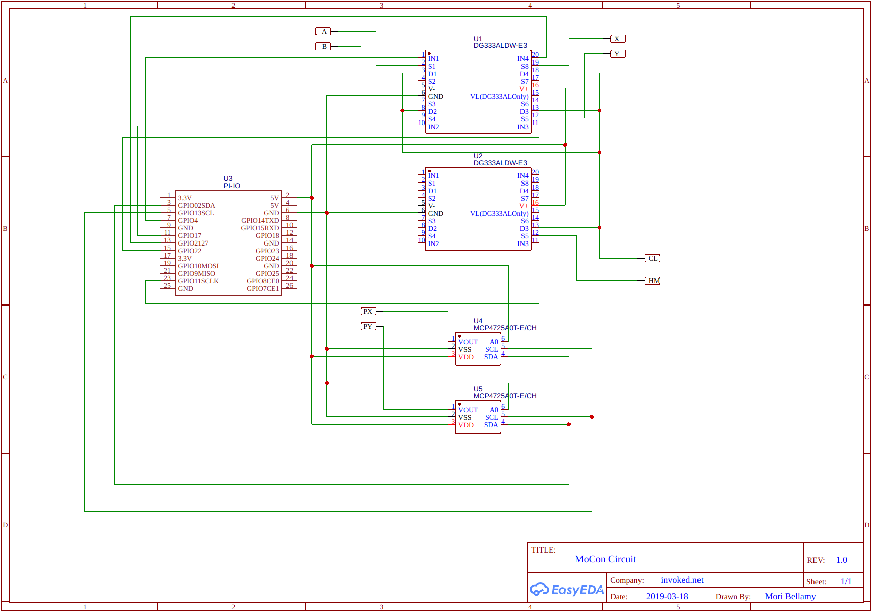
Now that you have a joycon with jumper wires sticking out of it, you can start to stimulate the circuit to emulate button presses. Here is the high level idea for the implementation:
| Component | Link | Function |
|---|---|---|
| PI-IO | raspi | Array of GPIO pins on the raspi, used to toggle analog switches and to drive an I2C bus. |
| DG333A Analog Switch (x2) | digikey | Single Pole, Double Throw switches. To bridge points to COL, emulating a button press. |
| MCP4725 (x2) | sparkfun | Digital Analog Converters. The pi sends a signal here to output a variable voltage, which will emulate what the joystick does. I bought breakout boards instead of the chip itself to make soldering easier. |
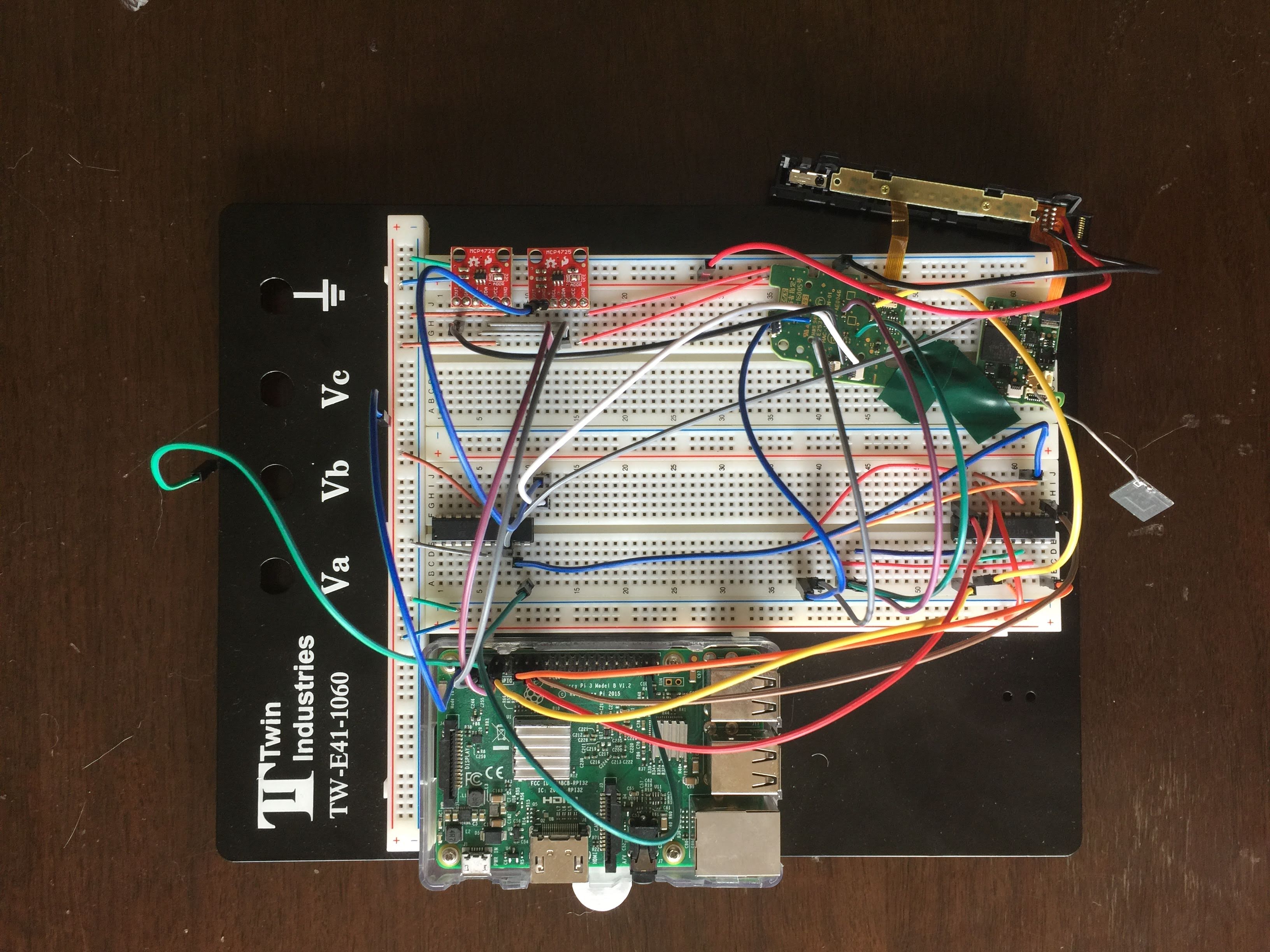
You’ll notice that the PI is powering all of the digital components. A separate power supply would really help. In my home setup, I noticed that a certain plug was delivering dirty power, which resulted in a bunch of button presses that I didn’t intend. Putting a capacitor across the rails of my circuit seemed to help, but really, the PI just isn’t designed to be a reliable power source.
While the circuit diagram is pretty to look at, my implementation is something else entirely:
The RasPi
Now that the custom circuit is ready to go, you just need the raspi to drive it. If you’ve followed along with the setup above, you can use my repo with minimal changes.
Update config.ini as needed, and power on your circuit and see if things work.
from pokemon_lets_go import *

press(HOME)  # Light array on slider should light up, pairing is being attempted
go_left()    # or up, down, right
press(A)     # or X, Y, B
Either now or later, you might run in to issues with the joysticks. The controller needs
a baseline voltage on POTX and POTY to register as “joystick untouched, it’s in the middle”.
Roughly, its .8V for “center”, less and more being a tilt in either direction. But if you followed
my instructions, the baseline voltage to the DACs is variable! For example, I have to adjust the
numbers depending on if my USB port is in use! In config.ini…
LR_NEUTRAL=680
UD_NEUTRAL=650
Use a number here between 0 and 4095, each representing a voltage between GND and VCC (which in my above circuit is 5V).
The camera
Now you can drive input from your raspi based on a script! All that remains is to decide what to do. Picking up 6 items in Rocket Corner is easy enough. I just did some trial and error for how long to go left, right, up, and down to get to each item. But how will I know to save the game when I get the desired result, as opposed to doing a soft reset and trying again?
I’m somewhat surprised, but still pleased, to report that a webcam + OCR is sufficient here.
You’ll need to rig up a sort of “studio” to grab screenshots of the switch. I used DVDs on either side of the USB-C power input
to prop up the whole console, and I put a webcam in front of that. Plugging the webcam into the PI, you can install and run
fswebcam to snap a picture!
But then how can you read it? Run tesseract on to your PI! Google maintains a debian release that, for me, installed without any problems. After installing the debian, install some python bindings:
# These are done as part of `pip install`, if you installed the GitHub repo.
pip install pillow
pip install pytesseract
And finally, tell the driver script the top-left coordinates of the dialog box for your studio:
DIALOG_UPPER_LEFT_X = 256
DIALOG_UPPER_LEFT_Y = 472
And then the magic can happen :). read_cropped_image() will start converting the game image to text.
driver.py uses that to figure out if a restart is needed.
Pulling it all together
Move your character to the entrance of rocket corner, then run
./pokemon_lets_go.py
to farm those Gold Bottlecaps. You’ll be a Pokémon master in no time ;).